Model by by Gary Zimmer
Projekt NM
Model by by Gary Zimmer
Description
They don't come much stranger than this. A three-view plan
can be found in Der Panzer-Kampfwagen Tiger und Seine
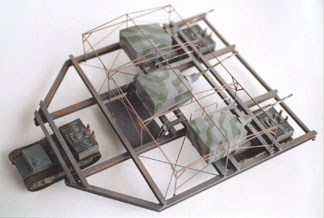
Abarten by Walter J. Speilberger of what appears to be three
large turrets, each with a 12.8cm gun, on an I-beam girder
frame measuring approximately 17 metres by 15 metres. It is
carried by three Tiger I chassis, two at the rear and one in
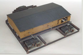
front (the guns face rearward). The frame is topped by a
rectangular wooden building that completely covers the
turrets except for the gun tubes. The building has three sets
of double doors, which when opened, allow some traverse and
elevation of the guns.Projekt NM only existed on the drawing
board, although all of its component parts were readily
available.
It only takes a cursory inspection of this machine to rule out
its use as a "tank". Firstly anything 15m wide would be
extremely awkward to manoeuvre anywhere. Tactical mobility
would be a problem, for to cross a waterway or ditch it would
require three bridges or one very wide one. In order to engage
the enemy, it must perform a stately U-turn in order for the
guns to bear. This may be feasible in open country, however
the building or shed covering the turrets would stand out
while performing no useful concealment function. It would be
of no more use for fighting other tanks than three separate
tanks would.
The only likely use for NM that I can see is some sort of
mobile coast defense battery, and I suspect it was probably a
Kreigsmarine project after all. If anyone else has a better
idea, please write to me. The reasons for this assumption are
as follows:
Disguising something as a building would only be of use where
it would not look out of place. Even a solitary building on
the coast would attract a lot less attention than three gun
turrets. I imagine this vehicle reversed into a position overlooking
some likely invasion beach, and pretending to be a harmless
wooden building. As drawn NM could be shifted between prepared
sites as a means of avoiding unwanted attention. I suspect the
building would be considered expendable once the shooting
started, and merely traversing the outer turrets would be
sufficient to clear most of the structure away.
Several hints point to German Navy involvement. Tank projects
tended to have either a VK number, or a name (e.g. "Lowe") or
some abbreviated descriptive name (e.g. NbFz). The
Kreigsmarine were big on letters, "H and "J" were battleship
projects, I believe. The extensive I-beam construction is
fairly normal for warships, not AFVs. Finally, the "building"
limits the vision of the gunners. However if the guns were
controlled by a director sited elsewhere, it would not be a
problem. Having several turrets aimed externally is something
navies have been doing for many years.
Weight of the whole assembly would be anybody's guess, however
there would be an upper limit of 165 - 180 tons, based on the
suspension capacity of the Tiger carriers.
Model by by Gary Zimmer
Making the model:
Despite its apparent complexity, it is actually an easy job
and even if you haven't scratchbuilt before, have a go.
Apologies to 1/35 modellers, I am into the small scales and
made my NM in 1/76, but there is no reason why it could not be
done in large scale (apart from finding somewhere to put it!).
Most of the comments below would still apply.
Tigers:
For the carriers I used Airfix Tigers. They are cheap to buy,
and although the tracks are rather plain, the rest of the kit
is quite acceptable. Of course Fujimi make a very nice (and
expensive) new Tiger, but I wasn't about to buy three of these
and cut them up. I made the lower hull and running gear as per
instructions. I cut the upper hull in front of the engine
deck, and behind the front (driver's) plate. This front plate
was cut down flush with the lower hull sides so the only
overhang is the engine compartment. As I assumed the carriers
would be unarmoured, I replaced the driver's visor with a
clear window. The rest of the vehicle was made from sheet
styrene.
Frame:
I simply scaled from the plans in Spielberger. The Airfix
tiger is 2.268 times as long as the Tiger carriers drawn on
the plan, so it is a simple matter to measure from the plans,
get out the calculator and multiply everything by 2.268. For
1/35 the magic number is 4.93.
I used Plastruct 1/4" (6.4mm) I-beam for the main frame, one
problem I found was that while it looks good for height, it is
too "square". I ended up cutting the flanges to make the beam
narrower. For this you need a tool such as a balsa stripper or
similar. Alternately, by using styrene strips you can make
your own I-beam (as I did when I ran out of store-bought.)
When making the frame, leave the diagonal I-beams at the front
until last. Assemble all the longtitudinal and lateral beams,
and before the glue sets measure from corner to corner. If the
diagonals are equal, everything is at 90 degrees. Note that
the beams that connect to the tank hulls are smaller, about
4.8mm high. The very front beam is C-section, not I-beam.
There was nothing in the plans to suggest how the Tiger
carriers connected to the frame. I made a guess that it would
be some sort of coupling or turntable, similar to that on a
prime mover except that so it does not twist the frame it
should be fully oscillating, in other words it should be able
to hinge side-to-side as well as fore-and-aft.
Turrets:
The turrets were made from pieces of 0.040" styrene sheet.
Nothing difficult. Note that the sides taper in at a different
place to where the roof slopes. The logical place for the
turrets to pivot from is midway between the two I-beams they
sit on, but that seems too far back. There are two further
smaller pieces of I-beam under the turret, these are not shown
as part of the main frame, I suspect they turn with the
turret. Barrels and mantlets were turned from solid styrene
rod, I used an electric drill as a poor man's lathe. I made
the guns movable by having a pivot just inside the turret
front. Each gun has a small lead weight inside the turret to
balance the weight of the barrel and mantlet.
Shed and doors:
The four walls were made from 0.020" styrene sheet. On the
sides I scribed parallel grooves about every 1/8" and then
roughed up the surface with a razor saw blade. This produces a
good wood-like finish on the surface. The roof was one 0.020"
sheet, bent to form the ridge. Before I assembled the shed, I
scribed and cut the doors from the rear wall. Door hinges were
made from small L-shaped pieces of fuse wire inside short
styrene rings cut from tube. I admit these aren't pretty, but
there doesn't seem to be a good alternative if you want 180
degree functional doors.
Other details:
The following is what I consider the finished assembly would
probably feature. When information on a vehicle is minimal, at
some stage the modeller sometimes has to resort to making an
educated guess. The alternative is to never finish anything
for fear of getting some trivial detail wrong.
The drawing in Spielberger seems to show some platform between
the centre turret and the lead carrier. It is not clear.
Assuming the crew would have to access the turrets, and at
some stage open the shed doors, I placed ladders and catwalks
in suitable places. I assumed the turrets would need doors in
either the sides or rear, the sides seemed most suitable. The
drawing appears to show attachment points for the shed frame,
I made a separate internal frame for the shed from 1.2mm
styrene rod. This locates in tube attached to the main frame,
and also serves to show the ghost outline of the shed when
displaying the model.
© Gary Zimmer
zimmer@bandicoot.me.rmit.edu.au